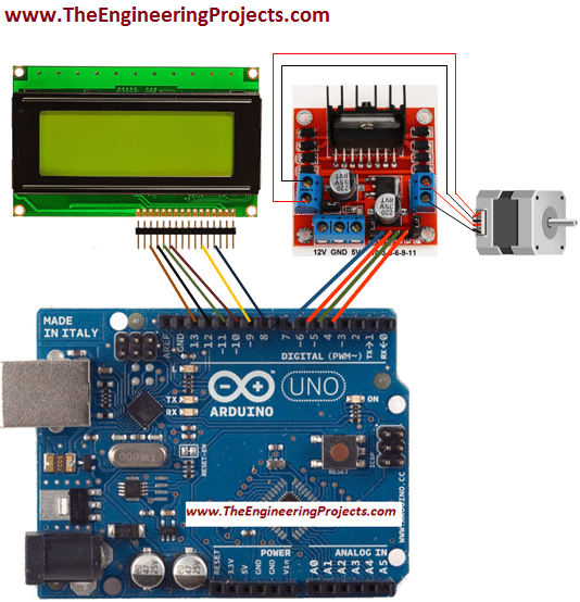

If there is are no pulses given- there will be no steps done by the drive and motor.ĭirection input pin can be LOW or HIGH all the time, while steps are made, depending on the direction needed. So drive can detect when new step command is given. After each step (HIGH) there must be (LOW) input for a moment. One sets the direction of rotation and other is for step commands.īut it’s not as simple as connecting steps pin into logical HIGH and expect the drive to move motor continuously. They usually have only 2 input pins which take commands in form of digital high and low. It makes correct windings to be excited in the correct way based on the input signals.
#4 WIRE STEPPER MOTOR ARDUINO CODE DRIVER#
The driver is doing the heavy lifting and it hides all the complexity behind a simple interface. This is where the driver comes into play. You could do this manually with some switches– step by step, but it has no practical use other than learning. DriverĪs we know- stepping motor can be moved one step at a time by applying electricity to coils in the correct order (and polarities). A microcontroller like in this case Arduino- gets its power from the USB cable or battery. I didn’t include a power supply for (micro)controller here since it’s self-explanatory. High overview of components needed to drive a stepper motor Commonly you need following parts to drive a stepper motor. So- what we need to get these motors going? Let’s break it down to components and explain each part briefly. But basics presented here is pretty universal and widely used in DIY community. Please read further down about more practical info about the drive and motor types. What do you need to get a stepper motor running?įollowing chapter is a very high overview. Controlling rotation and position is done through making correct amounts of steps. But if used correctly- there is no need anyway. Check out this excellent video on youtube which visualizes driving stepper motor by energizing coils in the correct order.Įven though they are used for accurate positioning, they don’t have any position feedback mechanisms like servos have. This means you have to make 200 steps to make a complete 360-degree turn (1.8 * 200). But motor will not run continuously- it holds the position while powered. The motor moves exactly one small predefined angle (called a step) each time coil(s) in motor get excited. Stepper motor’s rotation is controlled by exciting coils in correct order and polarity. They usually have 4 wires, but there is also a 5, 6 and 8 wire motors. They will not run by hooking up directly to the power supply. What you need to know is that stepper motors are not your average DC motors. Check out, for example, this article about stepper motor types.

But what the wiring should be? If it had 5 wires I would have done it like this schematics.There is a lot of resources online which go into great detail about different types of stepper motors and how they work. Since I do not have a driver at hand, I need to convert the circuit so it works with 4 transistors instead. And this is exactly the source of confusion: On arduino website, the sample circuit's stepper has 4 wires and is directly connected to a driver IC (a LMxxx), and the driver is connected to Arduino.

I use the MOSFETs as fast switches: 4 Arduino pins control 4 MOSFET transistors. But a 4-wire doesn't make sense! there must be 2 or 4 poles in a motor, and each pole needs a connection to common ground, so there must be 5 wires, how does a 4 wire work? I'm using MOSFET for driving the stepper, not LMxxxīecause I forgot to buy one, and I can't get my hands on one for a couple of days. All the pictures and circuits of easy tutorials I found on Google had 5 wires, (and those with 4 wires had different color coding anyway). Wires are colored: white, blue, red, yellow. Is it okay if my stepper motor has exactly 4 wires?
#4 WIRE STEPPER MOTOR ARDUINO CODE HOW TO#
Today I bought a stepper motor to play with, after 12 hours of struggling with it, I haven't been able to figure out how to connect it to an Arduino.

Simulate this circuit – Schematic created using CircuitLab


 0 kommentar(er)
